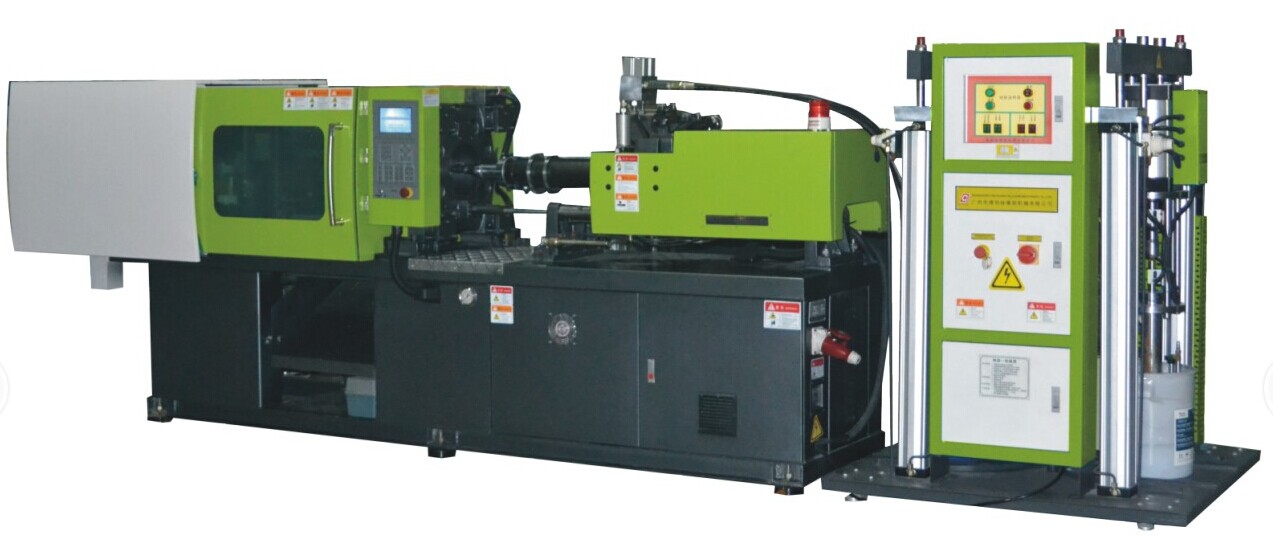
The machine is controlled by
a servo control system, which helps increase dynamic response and torque density
to the highest level and which replaces the tradition mode of driving that may
adopt a hydraulic, dc, stepping, or frequency control mechanism. Such a
configuration enables the system to have a shorter cycle, a higher production
rate, better reliability and a longer service life. The entire servo system
consists of a servo driver, a servomotor, an encoder and a load, which together
run in one control closed-loop system. Within the system, the driver receives
information from the outside, and then transmits it to the servomotor, which
converts the current into a torque and then passes it on to the load.
Upon
receipt of the torque, the load acts or accelerates or decelerates or
decelerates automatically, depending on its own characteristics. The encoder
measures the position of the servomoter and feeds the signal generated back to
the driver. Furthermore, the encoder is a high-precision controller and can
transmit modified values to the servo driver automatically, whereas the driver
retroacts the set values. The entire system functions as a high-responsive
closed-loop system. The DCM silica gel injection machine can save electricity by
40-80%, depending on the specific type of product. Normally, the thicker the
glue layer of a product and the longer the cooling time, the less the
electricity required.
1. Quicker response and higher precision.
2. A
shorter forming cycle and higher efficiency
3. Lower energy consumption on
the part of the motor
4. The current generated when starting a conventional
motor is generally 5 times as high as that maintained when in normal operation.
Because a DCM machine adopts soft start, it will not cause impact to the power
grid;
5. More water and oil-efficient
6. Lower noise
7. A shorter
machine body
8. A higher cost-performance ratio


Specification table for
the DCM servo energy-efficient silica gel injection
machine |
Model | Units | DCM-60 | DCM-90 | DCM-120 | DCM-160 |
screw
diameter | mm | Ø28 | Ø32 | Ø36 | Ø40 | Ø40 | Ø45 | Ø45 | Ø50 |
injection
pressure | Kg/cm2 | 2321 | 1777 | 1944 | 1575 | 2083 | 1645 | 2292 | 1856 |
injection
rate | cm3/sec | 70 | 92 | 106 | 131 | 135 | 170 | 138 | 170 |
screw
stroke | mm | 140 | 160 | 185 | 215 |
theoretical
volume | cm3 | 86 | 112 | 163 | 200 | 232 | 294 | 341 | 422 |
clamping
force | T | 68 | 92 | 120 | 167 |
demolding
stroke | mm | 450 | 500 | 560 | 640 |
minimum mold
thickness | mm | 150 | 180 | 200 | 220 |
maximum demolding
distance | mm | 600 | 730 | 760 | 860 |
space between tie
bars | mm | 320*320 | 360*360 | 425*425 | 460*460 |
Ejector
force | T | 2.7 | 3.3 | 3.9 | 5.3 |
Max hydraulic
pressure | Kg/cm2 | 140 | 140 | 140 | 140 |
Motor
power | KW | 7.5 | 11 | 15 | 18.5 |
Machine
weight | T | 2.7 | 3.6 | 4.5 | 6 |
Machine dimension
(L*W*H) | m | 4.1*0.9*1.5 | 4.2*1.3*1.6 | 5.1*1.0*1.6 | 5.5*1.0*1.7 |
20/200Kg feeding
machine | Weight | 500Kg | Size | m | 1.3*1.22*1.85/2.65 |
20Kg feeding
machine | Weight | 350Kg | Size | m | 1.2*1.0*1.9 |